Library LibIntegratedIoExt on MasterTool IEC XE
This tutorial presents the steps for inserting the LibIntegratedIoExt library into MasterTool IEC XE, in addition to configuring the function block AnalogInpuProbe, which allows you to use five additional analog inputs, in voltage or current mode, addressing it as the respective number to the PLC`s physical analog inputs (0, 1, 2, 3, 4). This allows the user to access the analog input through the block, even if the input is not configured in MasterTool or is configured in current/voltage mode. It is possible to use AI0.V and AI0.I simultaneously, for example.
Adding the LibIntegratedIoExt to a MasterTool IEC XE project
Open a project in MasterTool, double click on Library Manager then click “Add Library” and look for the “LibIntegratedIoExt” library.
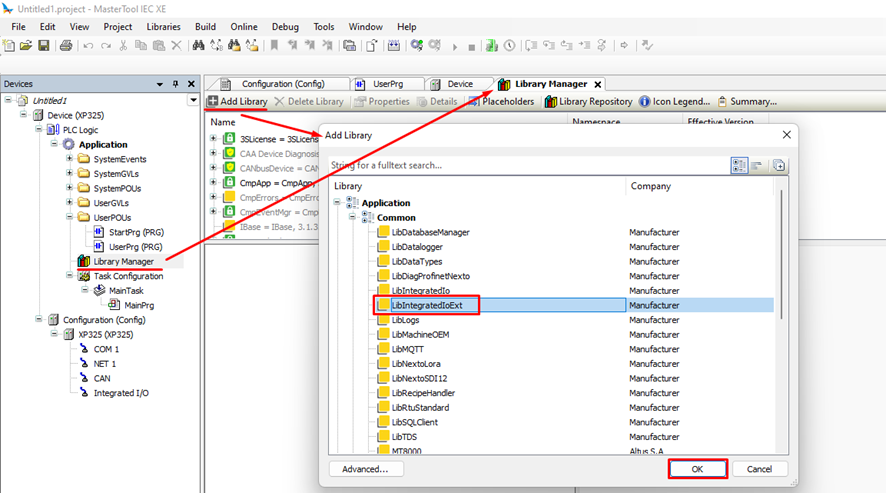
Click OK.
Declaring the function block AnalogInputProbe at StartPrg
This part of the tutorial is extremely important. The block can only be called in the StartPrg, because it only needs to be called once during the execution of the application. If the block is called in UserPrg or in a user-defined POU, its operation will not be guaranteed.
It is also necessary to declare a block for each analog input that you want to use.
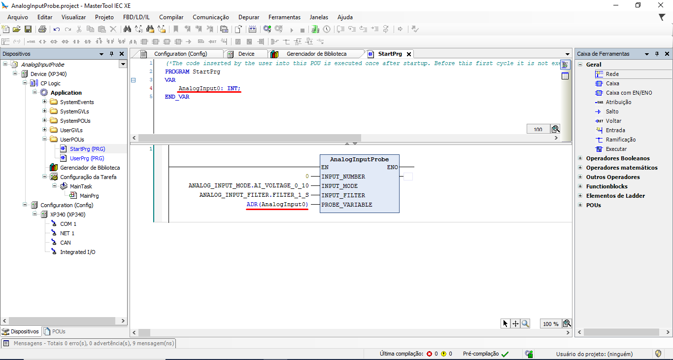
Access StartPg in the Device tree and insert an EN/ENO box. You must instantiate the block with the name "LibIntegratedIoExt.AnalognputProbe".
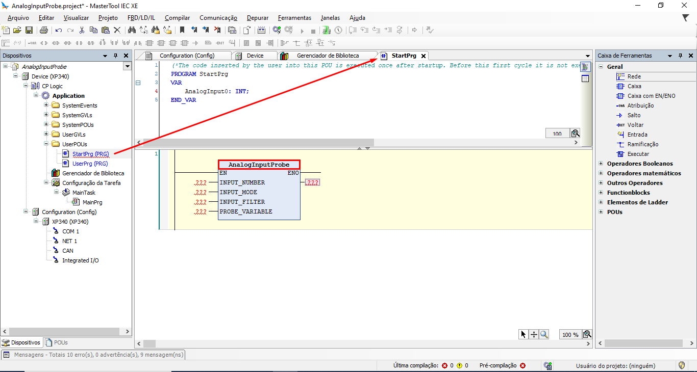
Then we must declare the FB input variables.
INPUT_NUMBER: Desired analog input number. Type: USINT;
INPUT_MODE: Analog input operating mode (available as values: AI_VOLTAGE_0_ 10, AI_CURRENT_4_20, AI_CURRENT_0_20 or AI_NOT_CONFIGURED). Type: ANALOG_INPUT_MODE;
INPUT_FILTER: Analog input filter type (100_ms, 1_s, 10_s). Type: ANALOG_INPUT_FILTER;
PROBE_VARIABLE: Address of the entire variable where the value of the respective analog input will be loaded. Type: POINTER_TO_INT;
AnalogInputProbe: Displays the block error code. Type: PROBE_ERROR_CODE.
To use the PROBE_VARIABLE parameter, you must declare a new INT variable and use the "ADR" address operator to assign the variable`s value to a pointer. In other words, this new variable takes on the value of the analog input.
As per the example used in the tutorial, the block were configured as follows.