Nexto Xpress - Getting Started
Welcome to Nexto Xpress’ first steps guide, your front gate to the Industry 4.0. In this guide, it will be demonstrated how to connect Nexto Xpress to the MasterTool IEC XE software, developing a simple application.
| Components
| |
| Software: | MasterTool IEC XE v3.23 |
|
|
|
| PLC: | XP325 |
|
|
|
Tutorial Sections
1. ARCHITECTURE
2. DEVELOPMENT
2.1. Electrical installation
2.2. MasterTool IEC XE
2.2.1. Creation of a Project
2.2.2. Developing the application
2.2.3. Configure analog inputs and outputs
2.2.4. Renaming referenced variables
2.2.5. Loading the application
3. RESULT
3.1. Simulation Mode
3.1.1. Manually write values to variables
3.1.2. I/O Simulator
4. EXTRA CONTENT
In the architecture used on this tutorial, the Ethernet port of XP325 was connected to the computer`s Ethernet port using the NX9202 cable.

2. DEVELOPMENT
This guide will demonstrate the development of a simple application in the MasterTool IEC XE software, where a digital input will trigger a digital output and the value of an analog input will be transferred to an analog output. Since there isn`t any switch/sensor connected to the PLC`s inputs (digital and analog), we will use a very interesting resource of the software, the Simulation mode.
It’s important to have the Xpress’ user manual in hand, since it will guide you on the technical features, mechanical installation, initial programming, settings and future maintenance.
Note: The developed application is available to download in the end of this tutorial.
2.1. Electrical installation
First, you need to power on your Xpress. To do this, simply connect the +V, 0V and Ground (if your power source has it) of the Xpress to a 24 Vdc power supply. When powering on the Xpress, all the LEDs will turn on, indicating that the equipment is initializing.
Note: If you have more questions about the Xpress` electrical installation, check the installation guide that comes with the product or access it by clicking here.
The MasterTool IEC XE software is the programming IDE of the Nexto series. To perform the development of projects in Xpress it is necessary to install this software by clicking here.
To facilitate the development of the projects, it is important to have MaterTool’s user manual in hand and the IEC 61131 programming manual, which contains information on programming languages, libraries and function blocks.
2.2.1. Creation of a Project
With MasterTool installed correctly, double-click on the icon that will show up on your Desktop.
The software will open. On start page, click on New Project to start the creation of a project.
The New Project window will open. In the Templates field, select MasterTool Standard Project (1), name the project in the Name field (2), and select the path which the project will be saved to through the three-point icon button in the Location field (3). Finally, click on OK (4) to continue creating the project.
As it has been selected to create a project with the standard template, Mastertool IEC XE Standard Project window will open. Choose the Xpress model you’re using and click Next.
In the next step you will be asked to choose the project profile and the default language for the programs. The PLCs of Nexto Xpress series only work with the Machine Profile project profile, so there isn’t need to change it. The programming language defined in this tutorial was Ladder. After choosing the default programming language, click on Next.
In this step you will be asked to choose the programming language for POUs UserPrg and StartPrg. As in the previous step the Ladder default language was defined, in this step both POUs will be with this language defined, so just click on Next.
Finally, click on Finish to finish creating the project.
2.2.2. Developing the application
With the project created in MasterTool, the logic will be developed to trigger a digital output through a digital input and transfer the value from an analog input to an analog output.
Referencing the Xpress’ inputs and outputs is slightly different from other Nexto family PLCs. Unlike the NX line where we attribute a variable to the point we want to use, in Xpress it isn’t necessary to declare, since they are declared by default.
• To reference a digital input, you must use: IXX, where XX is the input’s number itself;
• To reference a digital output, you must use: QXX, where XX is the output’s number itself;
• To reference an analog input, you must use: AIX, where X is the input’s number itself;
• To reference an analog output, you must use: AOX, where X is the output’s number itself.
Before starting the development of the application, it is important to highlight the function of the POUs present in the project. The StartPrg POU runs only on the first MainTask cycle, so any logic inserted in it will run only once. The POU UserPrg is run on each MainTask cycle, running the logic continuously. To facilitate and assist the organization of a project, it is recommended to create several POUs with different parts of the project and insert them in UserPrg so that they are executed at each MainTask cycle.
It is possible to view and insert POUs into the project tree. The project tree is on the left side of the software screen and contains several components that can be used in the development of a project. For this tutorial, we will create a POU called Operating containing the logic explained in the first paragraph, inserting it in UserPrg that is the programming POU.
In the project tree, right-click on UserPOUs, go to Add Object and click on POU.
The Add POU window will open. Insert the POU’s name (1), choose the POU’s type (2) and the programming language that will be used in it (3). Finally, click on Add (4).
The POU Operating tab will open on the right side of the Configuration tab automatically. In this tab the project logic will be developed. First, the logic developed to trigger a digital output from a digital input. On the right side of the screen, in Toolbox, expand the Ladder elements field and drag the Contact element to the option Start here.
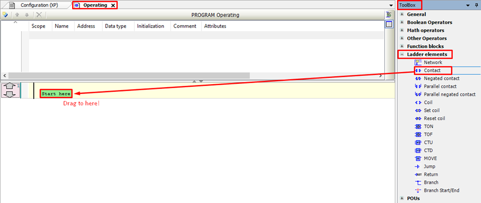
The element Contact will be inserted. Click on the ‘???’ field (1) above the element to change the name. As explained at the beginning of this subsection, to reference any digital input of Xpress just insert IXX, where ‘XX’ is the number of the digital input. In this tutorial we will use the input I00, so we will change the name of the element Contact to I00 (2).
In order for this digital input to trigger an output, an element Coil will be inserted. Again in the ToolBox, in the Ladder elements field, select the element Coil and drag it to the option Add output or jump here.
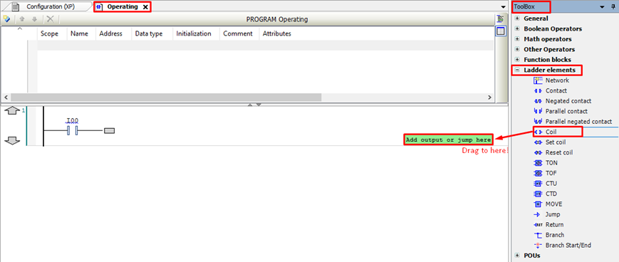
Change the name of the element Coil by inserting the digital output that will be used, as well as the element Contact. In this tutorial, we used the output Q00. The first logic network will look like the image below:

After, the logic to transfer the value from an analog input to an analog output will be developed. For that, still in the Ladder elements field, select Network and drag to the down arrow.
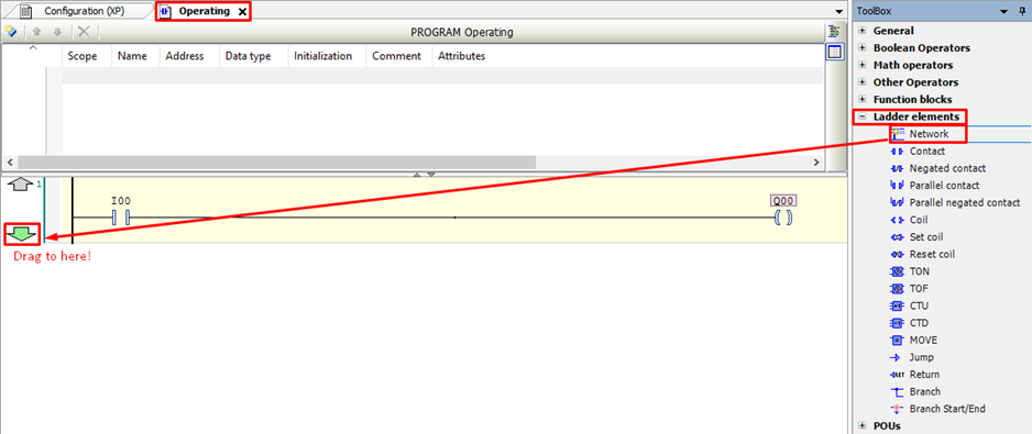
To insert the analog input and output, we will perform the same procedure as the one adopted in the digital input and output insertion, but the assigned names will be AI0 and AO0, respectively. The program developed in Operating must conform to the image below:
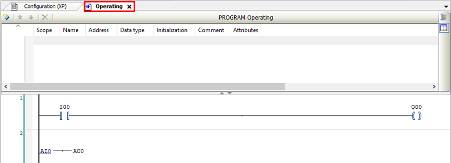
After developing the logic in the POU Operating, we will insert it in UserPrg so that it is executed at each MainTask cycle. To open the UserPrg POU tab in the project tree, double-click on UserPrg.
In the UserPrg tab, go to the ToolBox, expand the POUs field, select the Operating POU and drag to Start here.

The UserPrg POU will be as shown below:

2.2.3. Configure analog inputs and outputs
To use the analog inputs and outputs in the project, it is necessary to configure them. In this tutorial, we will configure the analog input AI0 and the analog output AO0 inserted in the Operating POU with the type Voltage 0 – 10 Vdc.
In the project tree, double-click on Integrated I/O.
The Integrated I/O tab will open. In the Analog Inputs tab, click on combo box of the Input Type of the Input AI0 and select Voltage 0 – 10 Vdc.
For the AO0 output configuration a similar procedure will be performed. In the Analog Outputs tab, click on combo box of the Output Type of the Output AO0 and select Voltage 0 – 10 Vdc.
2.2.4. Renaming referenced variables
As stated at the beginning of subsection 2.2.2. of this tutorial, in Xpress it isn’t necessary to declare the inputs and outputs, as they have already been declared by default. However, if you want to identify the inputs and outputs differently, it is possible to rename the variables, which by default have the name of the respective input or output.
For that, still in Integrated I/O, in the I/O Mapping tab it is possible to view all variables of inputs and outputs linked the physical inputs and outputs, expanding the fields.
Example: We will expand the Digital Inputs field and rename the variable linked to the digital input I00.
Expand the Digital Inputs field to view all digital inputs (1) and select the input you want to rename (00) (2).
Double-click on the selected variable and enter the name that the variable will assume. Enter to complete the change. Now the digital input 00 of Xpress was renamed to Surge1, as can be seen in the image below:
Thus, whenever it is need to use the digital input 00 in the project, the variable Surge1 should be used.
2.2.5. Loading the application
The Easy Connection feature of the Mastertool IEC XE is used to load the application in Xpress. This feature allows you to find, identify and change the Xpress network settings. With the PLC powered on as explained in section 2.1 of this tutorial, and connected to the computer according to the architecture shown in chapter 1, follow the steps of the video below that explain how to connect a Nexto series PLC to the computer.
It is important that the computer and PLC are on the same network. Xpress by default has IP: 192.168.15.1. Therefore, to connect to Xpress you will need to change computer IP, through of the video below or change the IP of your PLC, through the tutorial that explains how to change it, whose link is below:
https://www.altus.com.br/base-conhecimento/categoria/19/detalhe/360/nexto-xpress---ip-address-change
Note: The previously developed application is available for download at the end of this tutorial. So you can use it to test your Nexto Xpress PLC.
After the application is loaded in Xpress, in the top bar of the Mastertool IEC XE, click on Start to run the application in the PLC.

3.1. Simulation Mode
It is important to note that the Mastertool IEC XE software has an option to simulate the applications developed. This way, it is possible to test the application without being connected to the PLC, making the development more practical.
To activate Simulation mode, in the software’s top bar, click on Online, then click on Simulation.
To view the activation of the Simulation mode, just find the ‘SIMULATION’ message at the software’s bottom, as shown below:

Note: In Simulation mode it isn’t necessary to use the Easy Connection feature to login, as there is no need to physically connect to a PLC. Therefore, to login, just click on the Login button that is in the software’s top bar.
After perform Login on PLC, it is important click on Start to run the application.
3.1.1. Manually write values to variables
As stated in the introduction paragraph of chapter 2, there is no switch/sensor connected to the inputs (digital and analog) of the PLC to test the operation of logic. Therefore, we will use the feature to write values manually in these inputs.
To manually write a value in the digital input of logic, double-click on element Contact.

The Prepare Value window will open. Enter the TRUE value for true or FALSE for false and click on OK.
Note: It is important to note that the digital inputs and outputs are variables of type BOOL (boolean). Therefore, they only accept the values TRUE or FALSE.
To manually write a value in the analog input, double-click on the box next to the variable.
The Prepare Value window will open. Enter a value to assign to the input and click on OK.
Finally, to write the assigned values, go to the top bar, click on Debug, and then click on Write values.
Note: It is also possible to write the values using the keyboard shortcut Ctrl + F7.
According to the logic’s objective, the digital output will be triggered and the value of the analog input will pass to the analog output, as can be seen in the image below:

3.1.2. I/O Simulator
This tool is used in Simulation mode and is an alternative to the method of writing values manually (seen in subsection 3.1.1. of this tutorial). Unlike the method of writing values manually, this tool makes it possible to only simulate the physical inputs and outputs of the PLC.
With the project running in Simulation mode, at the right side of the screen the I/O Simulator will be displayed.
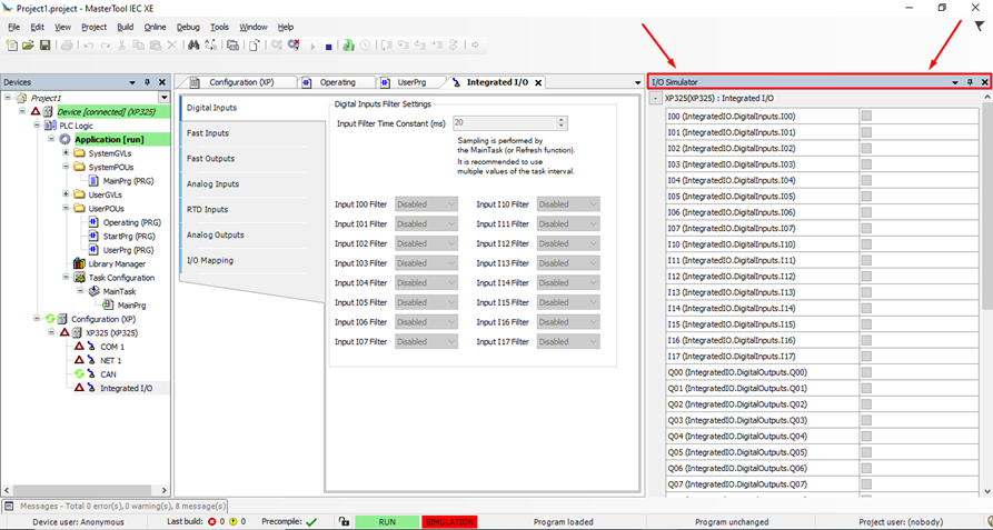
If it isn’t visible, on the top bar of the software, go to View and click on I/O Simulator.
In the I/O Simulator, it is possible to trigger the input by clicking on the square to it. The green square represents the input/output triggered.
Note: As planned from the development of the Operating POU, when turning triggering the input I00, the output Q00 is turned on.
The analog input value is simulated through a slider object that can be moved horizontally, varying the input value.
Note: As planned from the development of the Operating POU, the value of the AI0 analog input is transferred to the analog output AO0.
As part of the Nexto family, several tutorials that are available in the knowledge base can also be used with the Xpress. Click here to access them.
For more tips and tutorials visit our knowledge base.
