SOE configuration between Nexto and BluePlant
The SOE (Sequence of Events) is responsible for the generation of a sequence of digital events. Through the SOE it is possible to analyze the historic behavior of the system variables mapped in its monitoring area. The SOE is an exclusive service available for the NX3020 and NX3030 models.
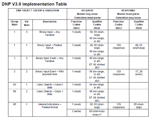
Once the SOE service is enabled, the CPU starts to behave as a DNP3 server, thus it is necessary the support to the DNP3 protocol by the client for the use of this resource. The supported object types as well as the function codes and the qualifiers can be found at "DNP3 Device Profile" (DNP3 Interoperability - Annex A, from Manual MU214605).
The SOE service uses the %Q addresses in order to form its base of static data. For it, it has to be set a continuous area of %Q memory where the user will inform its beginning and size. The DNP 3 first object address will always be 0, corresponding to %QBxxxx’s bit 0, where xxxx is the %Q initial address.
Thus, once defined the static database, the user must copy each digital point which should generate events within the %Q continuous area. The maximum number of points that can be copied is 8000.
More information can be found in chapter 5, item SOE Configuration, document MU214605.
Tutorial:
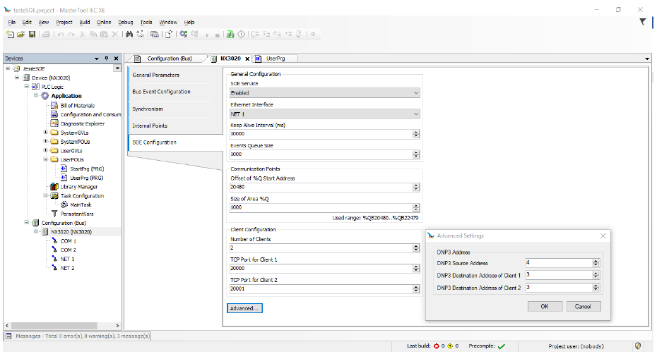
- The SOE service is enabled in the CPU configuration window (NX3020) on the "SOE Configuration" tab. Simply check the "Enabled" option in the first item, the other settings are defaults, and do not necessarily have to be changed. You should carefully have attention to the "Offset of %Q Start Address" (20480) of the "Communication Points" and the "TCP Port for Client 1" under "Client Configuration". The "Advanced ..." button has access to the DNP3 addresses of the Source (Server, in this case the NX3020 CPU) and the Destinations (Clients).
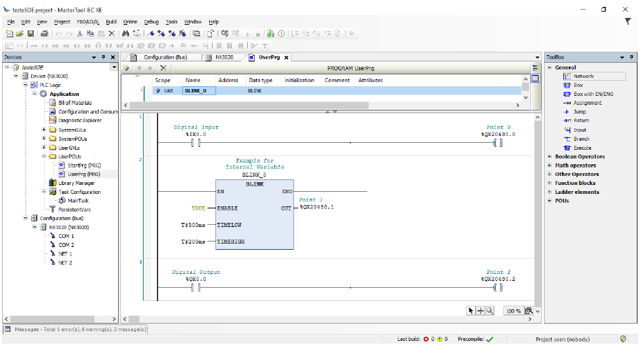
- For a demonstration of application of the events the logic was created below. `% QX20480.0` is the first point monitored by SOE, and in this case is triggered by a digital input. `% QX20480.1` is the second point controlled by a timer, which is FALSE for 500ms and TRUE for 200ms. `% QX20480.2` is the third point, recording the events of a digital output.
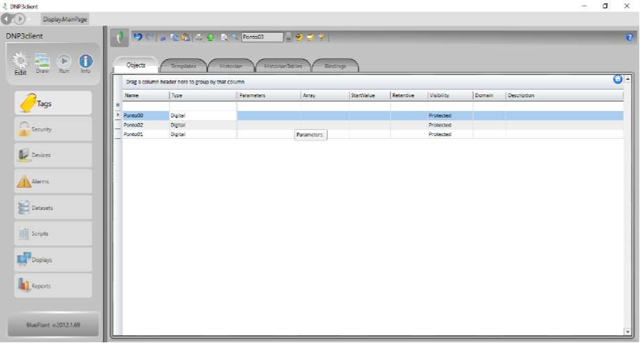
- The software used as the DNP3 Client for this demonstration is SCADA Blueplant. The first step in the software is to create Tags that are related to the PLC points.
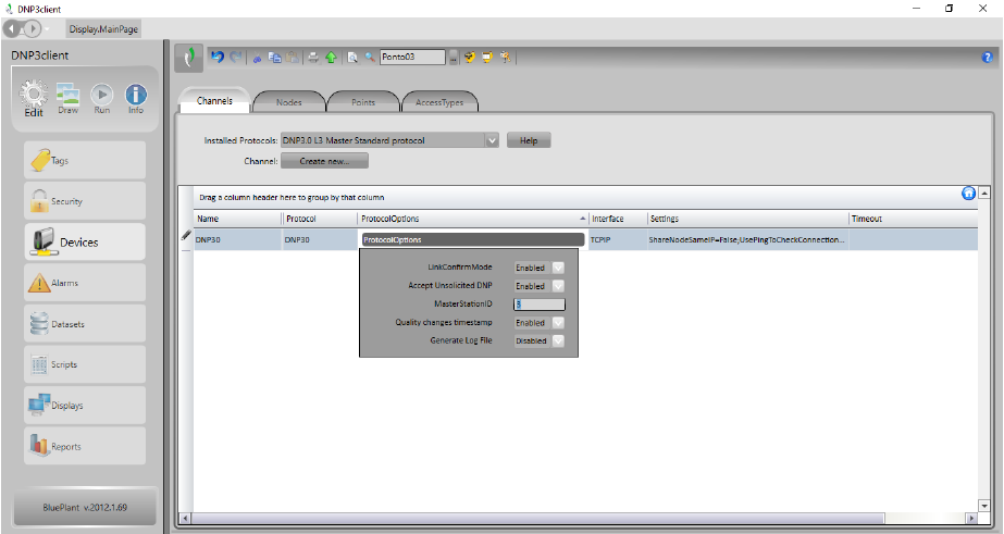
- After that step, the communication channel was created, and the protocol "DNP3.0 L3 Master Standard protocol" was chosen, in which the only modified parameter was the `MasterStationID`, set with the value `3`, same as the SOE configuration in MasterTool IEC XE software.
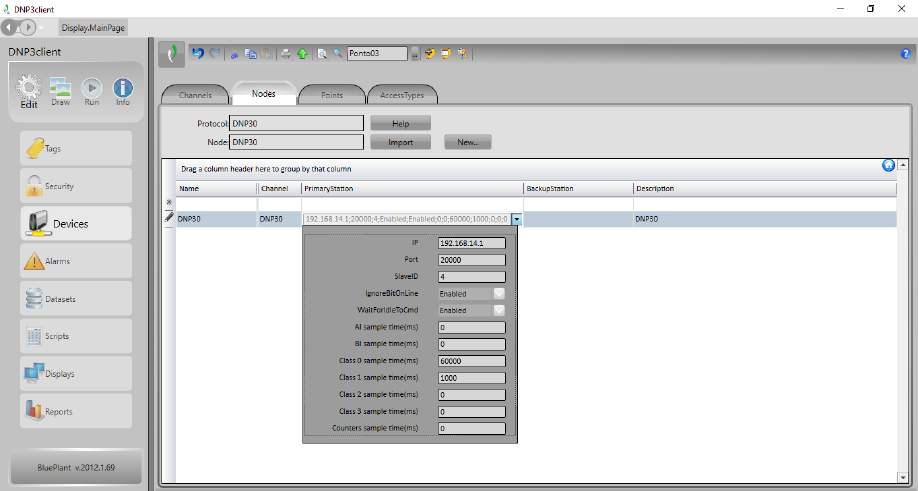
- Also in the Devices screen, the configuration to which node will be connected is made, identifying it with the address `IP` (192.168.14.1), `Port` (20000) and `SlaveIP` (4), values set on the server. The other parameters are default and can be left as they are.
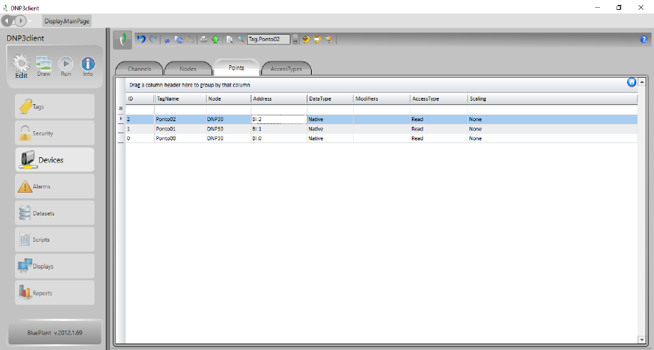
- The last step of this part is to configure the communication points using the previously created Tags. The type of point used is `Binary Input`, identifying the address of each point and following the sequence of addresses form the PLC. The timestamp is read by default, automatically in this case.
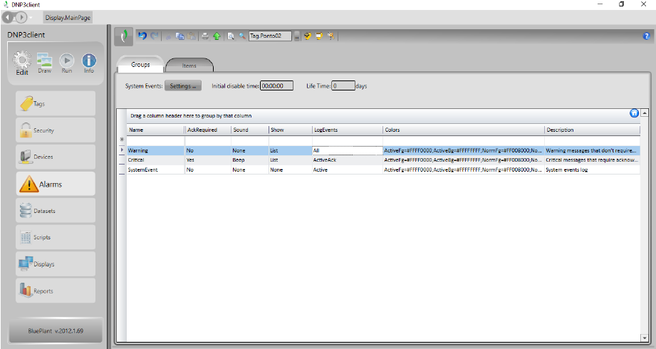
- In order to have access to the timestamp in the format of an event log in the Blueplant software is used the Alarms tool. For event logs only, the `Warning` alarm group is used by setting the `LogEvents` parameter to log all events.
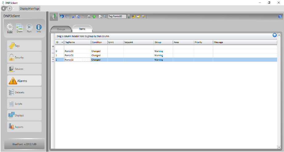
- Then the tags are added with the event logging condition set for any change of values.
- On the SCADA screen was added an alarm window, whose only changed parameters were the inclusion of the display of milliseconds in the timestamp and the choice to list "AlarmHistory + Events". Thus, the events generated by the PLC can already be observed when running the SCADA application, as in the image below.
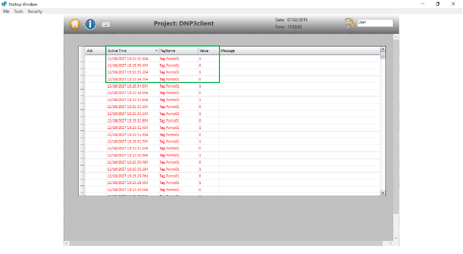
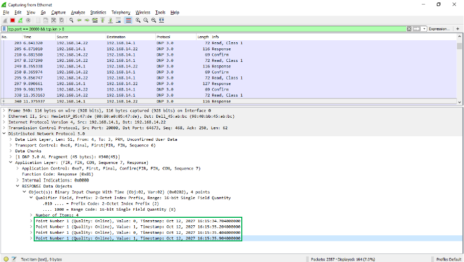
- By monitoring the DNP3 protocol through the Wireshark software, we can validate the time stamp information, where the only difference found was the time value, because of the time zone difference. Also it is observed the precise intervals between state change of the "Point 1", made by the timer in the PLC logic, remaining 200ms with value `1` and 500ms with value `0`.