Nexto Xpress - How to use additional analog inputs with the FB AnalogInputProbe
In this tutorial is described the procedure and orientations to use five additional analong inputs on your PLC through the function block AnalogInputProbe.
Components
Software: MasterTool IEC XE 3.34;
CLP: XP340 e XP325 (used in this tutorial, but all models with analog inputs support this function);
Firmware version: 1.11.14.0 (this expansion function is only available from this firmware version to further ones).
Tutorial Sections
1. ARCHITETURE
2. DEVELOPMENT
2.1. Inserting the library LibIntegratedIoExt on MasterTool IEC XE
2.2. Declaring he function block AnalogInputProbe on StartPrg
2.3. Electrical connections of the analog inputs
2.4. Executing the function block AnalogInputProbe
_____________________________________________________________________________________________
1. ARCHITETURE
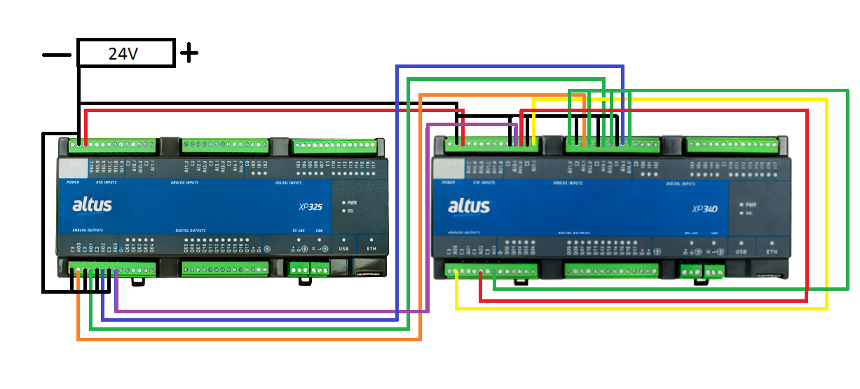
In the architeture of this tutorial,the PLC`s were supplied by a 24VDC voltage, the analog outpt AO0 from XP340 was connected to the analog input AI1.I ,the analog output AO2 was connected to the analog inputs AI0.V e AI2.V. The analog outpt AO0 from XP340 was connected to the analog input AI1.I ,the analog output AO2 was connected to the analog inputs AI0.V e AI2.V. The analog inputs AI0.V, AI3.V e AI4.V were connected to the analog output AO3 from XP340. The analog input AI0.I from XP340 was connected to the analog output AO0 from XP325, the analog input AI2.I was connected to AO1 from XP325,the analog input AI3.I was connected to the analog output AO2 also from XP325 and the analog input AI4.I was connected to the output AO3.
In this test all of the analong inputs of the PLC XP325 were not used. The inputs listed above belong to the PLC XP340.
After this, the XP340, the XP325 and the ethernet port of our computer were connected to a switch using the NX9202 cable.
2. DEVELOPMENT
This tutorial shows the steps to insert the library LibIntegratedIoExt on Mastertool IEC XE, along with the configuration of the function block AnalogInputProbe, that allows the user to use five additional analog inputs, in voltage or current mode, adressing it as the respective number of the physical input you wish to use (0, 1, 2, 3, 4). This block authorizes to use the analog input even if it is not configured on MasterTool Integrated Io or if it is configured as current/voltage. You will be able to use both voltage and current simultaneously.
It is necessary to point out the importance of having the manuals of th Nexto Xpresss series, so it is easier to consult at all parts of the application. This document will guide you on the techinical characteristics, the physical installation, the programming and configuraion of the PLC.
2.1. Inserting the library LibIntegratedIoExt on MasterTool IEC XE
Important: Both the library and the project used in this example will be available to download at the end of this tutorial.
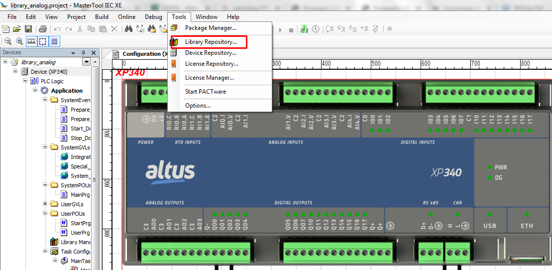
With a new project opened on MasterTool, select the tab "Tools".
Acess the the Library Repository.
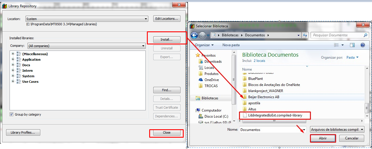
Select "Install" and then click on the library file.
Acess the Library manager, on the treeview.

Select the option "Add library", expand the items "Apllication" and "common" then select the library LibIntegratedIoExt.
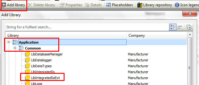
Click on "ok".
2.3. Declaring the function block AnalogInputProbe on StartPrg
This step of the tutorial is extremely important. The block can only be declared on StartPrg, because it needs to be executed just once. In case the block is declared on UserPrg or another specific POU, the correct function will not be guaranteed. It is also necessay to declare one block to every analog input that is going to be referenced.
Acess StartPg, on the treeview and insert a box EN/ENO. The block should be instanciated with the name "LibIntegratedIoExt.AnalogInputProbe".
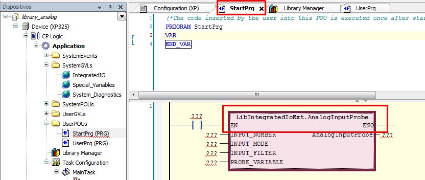
After this part is concluded, the variables of the block need to be declared.
INPUT_NUMBER: Number of the analog input referenced on the block. Type: USINT;
INPUT_MODE: Operation mode of the analog input (available as: AI_VOLTAGE_0_10, AI_CURRENT_4_20, AI_CURRENT_0_20, AI_NOT_CONFIGURED. Type: :ANALOG_INPUT_MODE;
INPUT_FILTER: The selected filter to the analog input (100_ms, 1_s, 10_s). Type: ANALOG_INPUT_FILTER;
PROBE_VARIABLE: Adress of the variable that will receive the value of the analog input. Type: POINTER_TO_INT;
AnalogInputProbe: This variable shows errors, if acused. Type: PROBE_ERROR_CODE.
To use the parameter PROBE_VARIABLE, it is necessary to declare a new variable with the type "INT" , then write the name of the respective variable with the command "ADR" to attribute the value to the pointer. It means that the new variable assumes the value of the analog input that was referenced.
2.4. Electrical connection of the analog inputs
This tutorial was written exclusively to demonstrate this new functionalitty of the xpress, so the method use to generate the signals to the analog inputs were derivated from the analog outputs of both PLC`s mentioned before. The values were forced on MasterTool.
The following connections, disponibilized on the Nexto Xpress manual, should be used to guarantee the correct perfomance of the device.
.png)
The negative signal of the power supply was derivated to the born 0V of the XP325 and XP340, just as was derivated to the borns C3 of the analog outputs in both PLC`s and the borns C2 on all analog inputs of the XP340. The positive sign was derivated to the born +V on both PLC`s.
The analog input AI0.I was connected to the analog output AO3 of the XP325. The analog input AI0.V was conected to the analog output AO2 of the XP340.
The analog input AI1.I was connected to the analog output AO0 of the XP340. The analog input AI1.V was conected to the analog output AO3 of the XP340.
The analog input AI2.I was connected to the analog output AO0 of the XP325. The analog input AI2.V was conected to the analog output AO2 of the XP340.
The analog input AI3.I was connected to the analog output AO1 of the XP325. The analog input AI3.V was conected to the analog output AO3 of the XP340.
The analog input AI4.I was connected to the analog output AO2 of the XP325. The analog input AI4.V was conected to the analog output AO3 of the XP340.
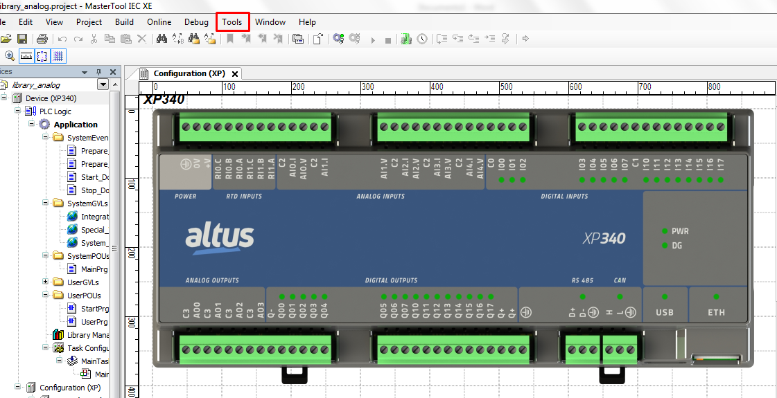
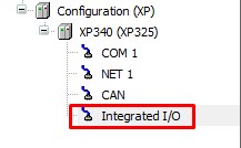
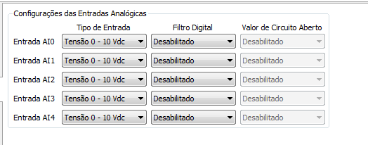
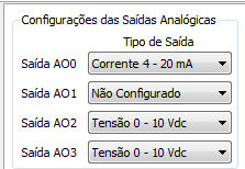
The configuration of the analog I/O on MastertTool is executed by the acess of Integrated I/O, at the treeview.
The I/O`s were configured as the following images.
XP340:
XP340:

XP325:

2.4. Executing the function block AnalogInputProbe
In this example, the peration mode of the analog inputs on Integrated I/O were configured as Voltage 0 - 10 VDC and were configured as Current 4 - 20mA on every block.
TAfter this, log on your PLC l with the ethernet cable NX9202.
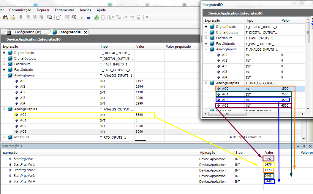
With the electrical connections made, and logged with our plc, values were forced on the analog output AO0, AO2 and AO3 of the XP340 and the analog outputs AO0, AO1, AO2, AO3. The analog output AO0 of the XP340 was configured as 4 - 20mA such as the outputs AO0, AO1, AO2 and AO3 of the XP325.
The analog outputs AO2 and AO3 of the XP325 were configured as Voltage 0 - 10 VDC.
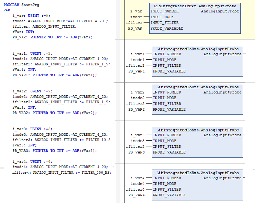
At the analog input rVar, it is possible to read the value 4442, which means that is receveing the signal of the analog output AO3 from XP325.
At the analog input rVar1 it is possible to read the value 5470, which means that is receveing the signal of the analog output AO0 from XP340.
At the analog input rVar2 it is possible to read the value 1473, which means that is receveing the signal of the analog output AO0 from XP325.
At the analog input rVar3 it is possible to read the value 2493, which means that is receveing the signal of the analog output AO1 from XP325.
At the analog input rVar4, it is possible to read the value 3440, which means that is receveing the signal of the analog output AO2 from XP325.
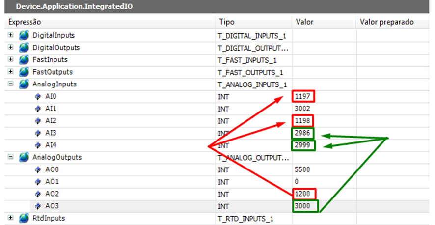
The analog output AO2 from XP340, configured as 0 - 10 VDC, the value 1200 was forced and can be readed, approximately, at the variable used on the parameter "PROBE_VARIABLE" e "PROBE_VARIABLE2", at the block AnalogInputProbe.
At the analog output from XP340, configured as 0 - 10 VDC, the value 3000 was forced and can be readed,approximately, at the variable used on the parameter "PROBE_VARIABLE1" e "PROBE_VARIABLE3" e "PROBE_VARIABLE4", on the block AnalogInputProbe.
CURRENT
VOLTAGE
Liked? Then share